Understanding Cable Impedance and Signal Matching
Cable impedance represents your cable’s combined opposition to alternating current, measured in ohms and determined by conductor geometry, dielectric materials, and physical dimensions rather than length. When you match impedances between your source, cable, and load—typically 50 or 75 ohms—you’ll eliminate signal reflections that cause power loss and data corruption. Mismatched impedances create standing waves, reduce signal-to-noise ratios, and introduce distortions that worsen at higher frequencies, making proper matching essential for maintaining signal integrity in everything from audio systems to high-speed networks where even minor mismatches compromise performance considerably.
We are supported by our audience. When you purchase through links on our site, we may earn an affiliate commission, at no extra cost for you. Learn more.
Notable Insights
- Cable impedance is the combined opposition to AC current, measured in ohms and determined by conductor geometry and dielectric materials.
- Characteristic impedance remains constant regardless of cable length and becomes critical when conductors approach 1/10 signal wavelength.
- Proper impedance matching between source, transmission line, and load prevents signal reflections and ensures efficient power transfer.
- Impedance mismatches cause signal reflections, power loss, standing waves, and degraded data integrity in transmission systems.
- LCR meters, network analyzers, and bridge methods are common tools for measuring impedance with varying frequency capabilities.
What Is Cable Impedance and How Does It Work
Electricity, much like water flowing through pipes, encounters resistance as it travels through cables, but there’s more to this story than simple opposition to current flow.
Cable impedance represents the combined opposition your transmission lines present to alternating current, incorporating both resistance and reactance components that affect signal behavior. When I examine different cable types, I find that characteristic impedance remains constant regardless of length, measuring the voltage-to-current ratio of traveling waves without reflections.
This fundamental property, measured in ohms, depends heavily on your cable’s geometry and dielectric materials. At RF frequencies, impedance becomes particularly significant when the conductor length approaches 1/10 wavelength of the signal. Understanding impedance helps you grasp why proper matching prevents signal reflections, ensuring efficient power transfer and maintaining signal integrity across your entire transmission system.
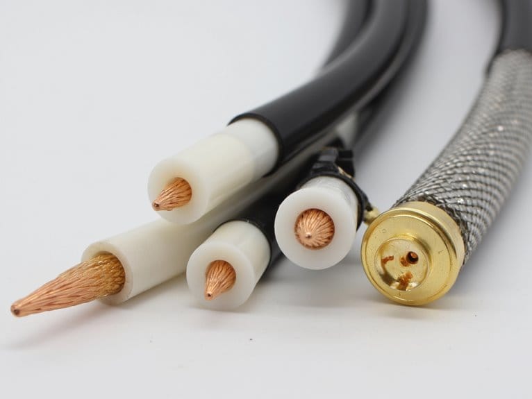
At high frequencies, insulation thickness becomes a critical factor in determining the overall impedance characteristics of your cable system.
Physical Factors That Determine Impedance Values
While understanding what cable impedance is gives you the foundation, I’ve found that grasping the specific physical factors behind those impedance values becomes much more practical when you’re selecting cables for your system.
The conductor properties, particularly the material’s electrical conductivity and surface finish, directly impact resistance and how current flows through your cable.
Dielectric effects from the insulating material between conductors determine capacitance through permittivity values, while geometrical dimensions like conductor diameter and spacing create the primary impedance characteristics.
Cable length won’t change your impedance value itself, though it affects signal quality over distance. Environmental factors may also alter the electrical properties of your cable, affecting overall impedance performance.
Frequency influences become critical at higher ranges where skin effect concentrates current near conductor surfaces, effectively increasing resistance.
The Critical Role of Impedance Matching in Signal Quality
Precision becomes everything when you’re dealing with signal transmission, and I’ve learned that impedance matching sits at the heart of achieving that precision in your cable systems.
When you align the impedances of your source, transmission line, and load, you’re fundamentally eliminating the reflections that would otherwise bounce back and create interference with your forward signals. This matching process delivers superior noise reduction by preventing standing waves that generate unwanted amplitude variations and phase shifts along your cable.
The result is dramatically improved signal fidelity, where your original waveform maintains its integrity from source to destination. I’ve found that even minor mismatches can introduce distortions that compound throughout your system, ultimately degrading performance and reliability in ways you mightn’t immediately notice.
Measuring and Calculating Cable Impedance
Once you move beyond understanding impedance matching theory, you’ll need to master the practical skills of actually measuring and calculating your cable’s impedance values, and I’ve discovered that choosing the right method can make the difference between accurate results and frustrating guesswork.
| Method | Best For | Key Limitation |
|---|---|---|
| LCR meters | L, C, R measurements for Z calculations | Manual calculation required |
| Bridge method | Low-frequency applications | Requires manual balancing |
| Network analyzers | Wide frequency range analysis | Needs recalibration per frequency change |
| RF I V method | High-frequency impedance testing | Transformer bandwidth restrictions |
You’ll find that LCR meters excel at measuring individual components, while network analyzers provide extensive frequency-dependent data that’s invaluable for RF applications.
Impact of Impedance on Signal Transmission Performance
When signal transmission encounters impedance mismatches along your cable system, the consequences ripple through every aspect of performance, creating a cascade of issues that I’ve seen frustrate engineers and technicians alike.
Signal reflections bounce back toward your source, interfering with subsequent transmissions and creating standing waves that distort amplitude and phase characteristics.
You’ll experience power loss as energy fails to transfer efficiently from source to load, particularly problematic at connector points where mismatches concentrate.
Data integrity suffers dramatically as these distortions degrade your signal-to-noise ratio, increasing bit errors and reducing transmission accuracy.
Frequency effects compound these problems exponentially—higher frequencies amplify reflection and attenuation issues, making proper impedance matching absolutely critical for maintaining reliable communication in modern high-speed applications.
Frequently Asked Questions
What Happens When You Connect Cables With Different Impedance Values Together?
When you connect cables with different impedance values, you’ll experience impedance mismatch effects that create signal reflection impact. These reflections reduce power transfer efficiency, cause signal distortion, and generate standing waves that degrade overall transmission quality.
Can Cable Impedance Change Over Time Due to Aging or Environmental Factors?
Yes, your cable’s impedance can change over time due to cable aging and environmental factors like heat, moisture, and radiation. These stressors degrade insulation properties, causing measurable impedance variations that affect signal integrity.
How Do You Fix Impedance Matching Problems in Existing Cable Installations?
You’ll install impedance matching transformers at cable termination points to bridge differences between cables and devices. Use matched splices for repairs and bridging networks to minimize signal loss without replacing existing cables.
What Are the Most Common Impedance Values Used in Different Industries?
You’ll find 50Ω dominates RF and telecommunications networks, while 75Ω rules video/cable TV. Audio systems often use 75Ω or 93Ω, and data cables typically run 100Ω for Ethernet applications.
Do Cable Connectors and Adapters Affect the Overall System Impedance Matching?
Yes, cable connectors and adapters greatly affect system impedance matching. Poor connector quality and inadequate adapter design create discontinuities that cause reflections, signal loss, and standing waves, degrading your overall system performance.
On a final note
Now that you’ve grasped how cable impedance operates, you’ll want to guarantee your system’s components match properly to avoid signal degradation. I’ve found that measuring impedance accurately, whether through time-domain reflectometry or network analyzers, prevents costly transmission issues down the line. You can’t ignore these fundamentals if you’re serious about maintaining signal integrity, especially in high-frequency applications where even small mismatches create significant performance problems.

