Understanding Ground Loops and How to Avoid Them
Ground loops form when you connect devices to different outlets with varying ground potentials, creating unwanted current paths that contaminate your signals with noise and interference. You’ll notice this as hum in audio systems or measurement errors in sensitive equipment, caused by circulating currents from voltage differences typically ranging 10-20 volts between grounding points. To prevent them, implement single-point grounding systems, use isolation transformers, and employ differential signaling techniques that reject common-mode interference-strategies that become increasingly critical as your electronic installations grow more complex.
We are supported by our audience. When you purchase through links on our site, we may earn an affiliate commission, at no extra cost for you. Learn more.
Notable Insights
- Ground loops occur when different points in a system have varying voltages, creating unwanted current paths that cause interference.
- They generate noise, signal corruption, and measurement errors in audio systems, communication equipment, and sensitive electronic devices.
- Implement single-point grounding systems to establish one centralized reference point and eliminate multiple problematic ground paths.
- Use isolation transformers, opto-isolators, and differential signaling techniques to interrupt ground currents and reduce interference susceptibility.
- Employ proper shield connections, star grounding topology, and regular maintenance to prevent dangerous voltage differences and equipment damage.
What Are Ground Loops and Why Do They Form?
In electrical systems, ground loops represent one of those frustrating phenomena that occur when two or more points in your system, which should theoretically maintain identical ground potential, end up with different voltages that create an unintended pathway for current flow.
Despite common misconceptions that proper grounding automatically prevents these issues, ground loops form because achieving perfect voltage equality across all grounding points remains practically impossible in real-world installations.
The voltage differences arise when current flows through grounding conductors that weren’t designed to carry it, often due to electromagnetic induction or neutral current from load imbalances. These grounding conductors should only provide a path for ground fault current and remain current-free under normal operating conditions.
Practical examples include audio equipment connected to different outlets producing that annoying hum, or multiple devices sharing interconnected cables while plugged into separate power sources, creating those problematic conductive loops. Ground potential between different outlets can vary significantly, with voltage differences of 10 to 20 volts commonly observed in building electrical systems.
How Ground Loops Impact Electronic Systems and Signal Quality
When you’ve got ground loops lurking in your electronic systems, you’ll quickly discover they’re like unwanted party crashers that generate noise, create interference, and generally make a mess of your carefully planned signal pathways.
These loops don’t just sit quietly in the background-they actively degrade your equipment’s performance by introducing hum, buzz, and various forms of signal corruption that can turn crystal-clear audio into something that sounds like it’s coming through a tin can.
I’ve seen countless situations where these seemingly innocent electrical phenomena destabilize signals, reduce measurement accuracy, and create headaches that range from minor annoyances to complete system failures. The root cause typically stems from multiple grounding points within your electrical system, which creates those unintended current paths that wreak havoc on signal integrity.
Noise and Interference Generation
Ground loops transform otherwise quiet electronic systems into sources of frustrating noise and interference, creating a cascade of problems that I’ve witnessed ruin everything from home audio setups to critical measurement equipment.
When circulating currents flow through these unwanted loops, they couple into your signal lines, causing signal contamination that degrades the signal-to-noise ratio and makes effective noise cancellation nearly impossible.
You’ll notice this interference as humming in audio systems, static in communication equipment, or measurement errors in data acquisition setups. The voltage offsets created between interconnected devices disrupt normal operation, while electromagnetic interference from nearby AC power lines and motors amplifies the problem, creating unpredictable noise that varies with environmental conditions and system loads.
Signal Stability Problems
Beyond the obvious noise issues I’ve already covered, ground loops create a more insidious problem that I’ve seen destroy the reliability of countless electronic systems: they make your ground reference-the very foundation that all your signals depend on-completely unstable.
When interference currents flow through your ground wires, the inherent resistance converts these currents into voltage fluctuations that constantly shift your reference point, causing signal distortion and measurement errors that’ll drive you crazy trying to troubleshoot.
These voltage offsets reduce your digital signals’ dynamic range while creating impedance mismatches that increase susceptibility to interference, leading to data corruption, dropped packets, and bit errors.
In analog systems, you’ll notice degraded signal-to-noise ratios and inaccurate readings that make precise measurements nearly impossible to achieve consistently.
Equipment Performance Degradation
These reference point issues I’ve described represent just the tip of the iceberg when it comes to how ground loops systematically degrade your equipment’s performance, often in ways that aren’t immediately obvious until you’re troubleshooting mysterious system failures at 2 AM.
Ground loops corrupt data transmission, causing equipment to malfunction with erratic behavior that’ll drive you nuts during critical operations. Digital electronics suffer reduced dynamic range due to ground voltage offsets, making systems more susceptible to interference and communication errors.
Poor circuit design compounds these problems when proper grounding techniques aren’t implemented from the start. Leakage currents flow through these unintended paths, damaging sensitive components through unexpected voltage stresses, while feedback acts like electrical noise that degrades low-level sensor accuracy and measurement precision throughout your entire system.
Essential Grounding Principles for Loop Prevention
You can effectively prevent ground loops by implementing three fundamental strategies that I’ve found work consistently across various electronic installations, regardless of complexity or scale.
First, you’ll want to establish a single point grounding system that creates one centralized reference point, eliminating the multiple ground paths that typically cause unwanted current circulation between connected devices.
Additionally, you should consider differential signaling techniques and proper shield connection methods, both of which greatly reduce your system’s susceptibility to ground-related interference while maintaining signal integrity throughout your entire setup.
Single Point Grounding
When multiple ground paths create circulating currents that wreak havoc on your system’s performance, I’ve found that single-point grounding offers one of the most effective solutions for preventing ground loops in low-frequency applications. This technique connects all system grounds to one physical reference point, eliminating the formation of troublesome loops that cause interference and noise.
The single point benefits become immediately apparent when you’re dealing with sensitive analog circuits or thermal control signals, where even minor ground potential differences can compromise signal integrity.
You’ll discover that proper grounding techniques involve choosing between series configurations, which require less wiring but risk common impedance coupling, and parallel setups that provide superior noise immunity despite increased complexity and longer wire runs for your installations.
Differential Signaling Techniques
Moving beyond single-point grounding solutions, I’ve discovered that differential signaling techniques offer one of the most robust approaches for preventing ground loops while maintaining excellent signal integrity across your system.
This method transmits information using two complementary signals, which creates exceptional differential capacity for noise rejection while providing superior signal isolation from ground potential differences.
The key advantages I’ve observed include:
- Common mode rejection – measures voltage differences rather than absolute voltages, effectively canceling ground loop interference
- Balanced transmission – reduces EMI through symmetric signal paths that behave like twisted pairs
- Ground independence – doesn’t require perfect common ground between sender and receiver
- Higher data rates – enables faster communication with lower voltage levels due to improved signal-to-noise ratios
Shield Connection Methods
While differential signaling provides excellent noise immunity through balanced transmission, the physical shield surrounding your cables represents another critical defense layer that requires careful consideration of how and where you connect it to ground.
The fundamental principle involves choosing between single-point grounding, which breaks ground loops by connecting only one shield end to your system’s master ground, and dual-end grounding for high-frequency applications above 100 kHz where skin effect reduces interference.
Different shield types require specific grounding techniques: braided shields offer mechanical robustness for low-frequency environments, while foil shields excel at high-frequency protection with easier handling.
I’ve found that hybrid approaches often work best, combining controlled grounding methods that prevent low-frequency ground loops while maintaining electromagnetic shielding effectiveness across mixed-signal environments.
Effective Techniques and Solutions for Ground Loop Mitigation
Ground loops might seem like insurmountable electrical gremlins, but I’ve found that systematic mitigation techniques can effectively eliminate these noise-inducing pathways in most installations.
Ground loops may appear as mystifying electrical demons, but systematic approaches can tame these interference-creating circuits in virtually any setup.
You’ll want to focus on breaking unwanted current paths while maintaining proper safety grounding throughout your system.
The most effective solutions I’ve implemented include:
- Isolation transformers and opto-isolators to electrically separate components and interrupt ground current flow
- Star grounding topology connecting all equipment to a single central ground point, minimizing voltage differences
- Grounding bars or busbars to consolidate multiple ground connections physically, reducing loop areas that pick up interference
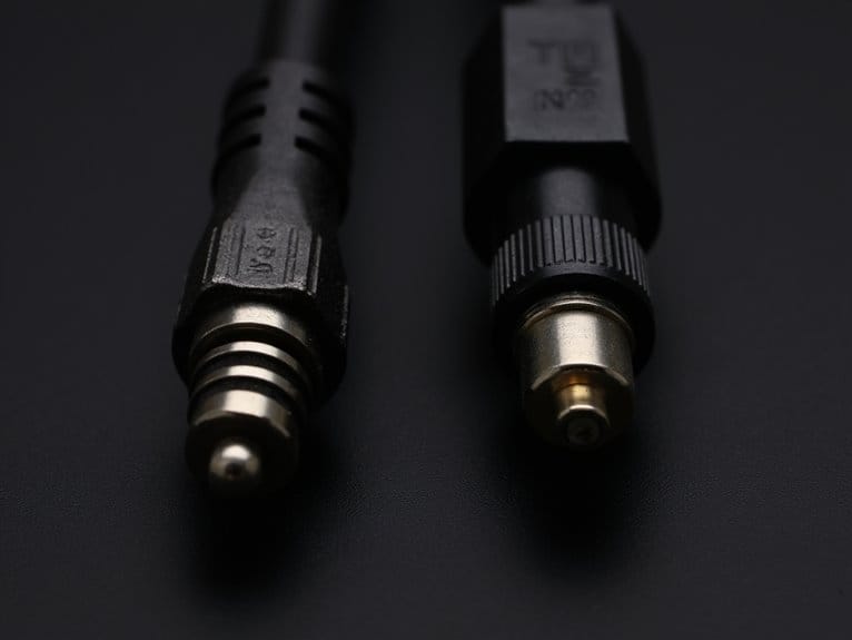
- Single-point shield grounding using shielded cables connected to ground at only one end, preventing EMI-induced currents
These techniques, combined with proper wire gauge selection and balanced connections, will resolve most ground loop issues you’ll encounter.
Common Real-World Scenarios Where Ground Loops Occur
Throughout my years troubleshooting electrical systems, I’ve discovered that ground loops consistently emerge in predictable scenarios where multiple grounding paths create unintended current flows.
Industrial environments present the most challenging situations, where large facilities rely on multiple grounding points rather than single-point star configurations, creating voltage differences that drive unwanted currents through grounding conductors.
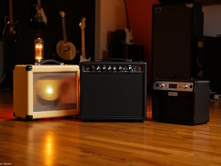
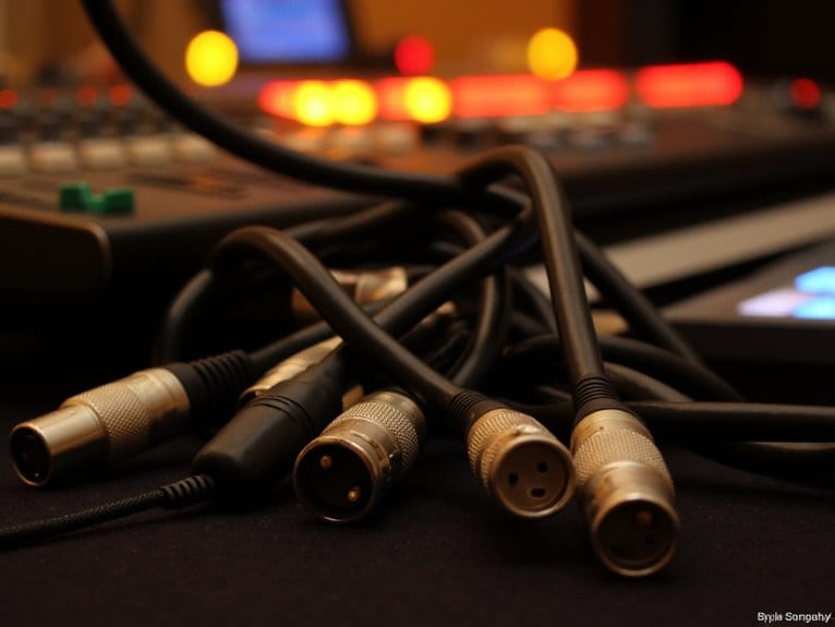
Audio systems suffer particularly from ground loops when equipment connects to different electrical outlets with varying ground potentials, producing that familiar annoying hum.
In data centers and commercial facilities, complex electrical installations with distributed power sources create multiple grounding references, while building wiring often develops ground loops during renovations when additional grounding points are added.
Signal transmission between equipment becomes compromised, and these installation challenges require careful planning to maintain proper grounding hierarchy.
Safety Considerations and Equipment Protection Strategies
Beyond the technical nuisance of unwanted currents and electrical noise, ground loops pose genuine safety risks that can’t be ignored in any electrical installation.
When voltage differences develop between grounding points, dangerous currents can flow through equipment chassis, creating shock hazards that threaten personnel safety and equipment integrity.
Effective grounding strategies protect both people and equipment through several key approaches:
- Single Reference Point: Establish one well-defined ground reference across all signal and power circuits to minimize loop currents.
- Proper Bonding: Follow NEC guidelines to prevent improper neutral-to-ground connections that create hazardous parallel paths.
- Isolation Techniques: Deploy transformers or opto-isolators to interrupt ground loops in sensitive electronic systems.
- Regular Maintenance: Inspect ground connections routinely to prevent corrosion-induced resistance increases.
These protection strategies guarantee compliance while safeguarding your investment.
Frequently Asked Questions
Can Ground Loops Cause Permanent Damage to Expensive Audio Equipment?
Ground loop effects typically won’t cause permanent damage to your expensive audio equipment. They create annoying hum rather than harmful electrical stress. However, you’ll want proper equipment protection since incorrect fixes can compromise safety.
How Much Does Professional Ground Loop Isolation Equipment Typically Cost?
You’ll find professional ground loop isolation equipment prices range from $100-$310, with basic consumer models costing $15-$60. Professional units offer multiple channels, bass restoration, and enhanced build quality that justifies higher isolation equipment costs.
Are Wireless Connections Immune to Ground Loop Interference Issues?
Yes, you’ll find wireless technology completely avoids ground loop problems since there’s no physical conductive path between devices. However, wireless connections can still experience other types of signal interference like radio frequency or electromagnetic disruption.
Do Ground Loops Affect Battery-Powered Devices Differently Than Ac-Powered Ones?
Battery-powered devices experience fewer ground loop issues since they’re isolated from mains ground, improving battery performance. However, you’ll still face problems during device interaction when connecting multiple units or mixing with AC-powered equipment.
Can Building Age or Construction Materials Increase Ground Loop Susceptibility?
Yes, your building’s age factors considerably affect ground loop susceptibility since older structures have less robust grounding systems. Additionally, building materials like steel frames provide better grounding paths than wood construction.
On a final note
You’ve now got the knowledge to tackle ground loops head-on, and honestly, it’s not as intimidating as it first seems. By implementing proper grounding techniques, using isolation transformers, and maintaining clean signal paths, you’ll protect your equipment and preserve signal integrity. Remember to identify potential loop paths early, apply star grounding where possible, and don’t hesitate to invest in quality isolation equipment when needed.